There are two main methods to detect gravitational waves which have been implemented in the currently
working instruments. One method is to measure changes induced by gravitational waves on the
distances between freely moving test masses using coherent trains of electromagnetic waves. The
other method is to measure the deformation of large masses at their resonance frequencies
induced by gravitational waves. The first idea is realized in laser interferometric detectors and
Doppler tracking experiments [82, 65] whereas the second idea is implemented in resonant mass
detectors [13![]() ].
].
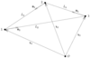
Let us consider the response to a plane gravitational wave of a freely falling configuration of masses. It is
enough to consider a configuration of three masses shown in Figure 1![]() Update
Update![]() to obtain the response for all currently working and planned detectors. Two masses model a
Doppler tracking experiment where one mass is the Earth and the other one is a distant spacecraft. Three
masses model a ground-based laser interferometer where the masses are suspended from seismically isolated
supports or a space-borne interferometer where the three masses are shielded in satellites driven by
drag-free control systems.
to obtain the response for all currently working and planned detectors. Two masses model a
Doppler tracking experiment where one mass is the Earth and the other one is a distant spacecraft. Three
masses model a ground-based laser interferometer where the masses are suspended from seismically isolated
supports or a space-borne interferometer where the three masses are shielded in satellites driven by
drag-free control systems.
In Figure 1![]() we have introduced the following notation:
we have introduced the following notation: ![]() denotes the origin of the TT coordinate
system related to the passing gravitational wave,
denotes the origin of the TT coordinate
system related to the passing gravitational wave, ![]() (
(![]() ) are 3-vectors joining
) are 3-vectors joining ![]() and the
masses,
and the
masses, ![]() and
and ![]() (
(![]() ) are, respectively, 3-vectors of unit Euclidean length along the lines
joining the masses and the coordinate Euclidean distances between the masses, where
) are, respectively, 3-vectors of unit Euclidean length along the lines
joining the masses and the coordinate Euclidean distances between the masses, where ![]() is the label of the
opposite mass. Let us also denote by
is the label of the
opposite mass. Let us also denote by ![]() the unit 3-vector directed from the origin
the unit 3-vector directed from the origin ![]() to the source of the
gravitational wave. We first assume that the spatial coordinates of the masses do not change in
time.
to the source of the
gravitational wave. We first assume that the spatial coordinates of the masses do not change in
time.
Let ![]() be the frequency of the coherent beam used in the detector (laser light in the case of an
interferometer and radio waves in the case of Doppler tracking). Let
be the frequency of the coherent beam used in the detector (laser light in the case of an
interferometer and radio waves in the case of Doppler tracking). Let ![]() be the relative change
be the relative change ![]() of
frequency induced by a transverse, traceless, plane gravitational wave on the coherent beam travelling from
the mass
of
frequency induced by a transverse, traceless, plane gravitational wave on the coherent beam travelling from
the mass ![]() to the mass
to the mass ![]() , and let
, and let ![]() be the relative change of frequency induced on the beam
travelling from the mass 3 to the mass 1. The frequency shifts
be the relative change of frequency induced on the beam
travelling from the mass 3 to the mass 1. The frequency shifts ![]() and
and ![]() are given by [37, 10, 83]
are given by [37, 10, 83]
Real gravitational-wave detectors do not stay at rest with respect to the TT coordinate system related
to the passing gravitational wave, because they also move in the gravitational field of the solar system
bodies, as in the case of the LISA spacecraft, or are fixed to the surface of Earth, as in the case of
Earth-based laser interferometers or resonant bar detectors. Let us choose the origin ![]() of the TT
coordinate system to coincide with the solar system barycenter (SSB). The motion of the detector with
respect to the SSB will modulate the gravitational-wave signal registered by the detector. One can show
that as far as the velocities of the masses (modelling the detector’s parts) with respect to the SSB are
nonrelativistic, which is the case for all existing or planned detectors, the Equations (1
of the TT
coordinate system to coincide with the solar system barycenter (SSB). The motion of the detector with
respect to the SSB will modulate the gravitational-wave signal registered by the detector. One can show
that as far as the velocities of the masses (modelling the detector’s parts) with respect to the SSB are
nonrelativistic, which is the case for all existing or planned detectors, the Equations (1![]() ) and (2
) and (2![]() ) can
still be used, provided the 3-vectors
) can
still be used, provided the 3-vectors ![]() and
and ![]() (
(![]() ) will be interpreted as made
of the time-dependent components describing the motion of the masses with respect to the
SSB.
) will be interpreted as made
of the time-dependent components describing the motion of the masses with respect to the
SSB.
It is often convenient to introduce the proper reference frame of the detector with coordinates ![]() .
Because the motion of this frame with respect to the SSB is nonrelativistic, we can assume that the
transformation between the SSB-related coordinates
.
Because the motion of this frame with respect to the SSB is nonrelativistic, we can assume that the
transformation between the SSB-related coordinates ![]() and the detector’s coordinates
and the detector’s coordinates ![]() has the
form
has the
form
For a standard Michelson, equal-arm interferometric configuration ![]() is given in terms of one-way
frequency changes
is given in terms of one-way
frequency changes ![]() and
and ![]() (see Equations (1
(see Equations (1![]() ) and (2
) and (2![]() ) with
) with ![]() , where we assume
that the mass 1 corresponds to the corner station of the interferometer) by the expression [93]
, where we assume
that the mass 1 corresponds to the corner station of the interferometer) by the expression [93]
In the case of a bar detector the long-wavelength approximation is very accurate and the detector’s
response is defined as ![]() , where
, where ![]() is the wave-induced change of the proper length
is the wave-induced change of the proper length
![]() of the bar. The response
of the bar. The response ![]() is given by
is given by
In most cases of interest the response of the detector to a gravitational wave can be written as a linear
combination of four constant amplitudes ![]() ,
,
Equation (14![]() ) is a model of the response of the space-based detector LISA to gravitational waves from a
binary system [60
) is a model of the response of the space-based detector LISA to gravitational waves from a
binary system [60![]() ], whereas Equation (15
], whereas Equation (15![]() ) is a model of the response of a ground-based detector to a
continuous source of gravitational waves like a rotating neutron star [50
) is a model of the response of a ground-based detector to a
continuous source of gravitational waves like a rotating neutron star [50![]() ]. The gravitational-wave signal
from spinning neutron stars may consist of several components of the form (14
]. The gravitational-wave signal
from spinning neutron stars may consist of several components of the form (14![]() ). For short observation
times over which the amplitude modulation functions are nearly constant, the response can be
approximated by
). For short observation
times over which the amplitude modulation functions are nearly constant, the response can be
approximated by
| http://www.livingreviews.org/lrr-2005-3 | This work is licensed under a Creative Commons Attribution-Noncommercial-No Derivative Works 2.0 Germany License. Problems/comments to |